This guide assumes somewhat advanced networking knowledge and at-least some knowledge in Linux and Windows servers. This is not the recommended method for setting up tunnels / GRE on Windows. See instead our .exe based single application system that does not require virtualization.
Requirements:
- This can be run on a KVM virtualized Windows installation, although it is recommended that it is performed on a Physical Dedicated Server in production.
- At least 512MB RAM, at-least 150MB ram should be free to run the Virtual Machine.
- A Windows Server with at-least 2 public IP Addresses (NAT + DMZ can be used but is not covered in this tutorial).
- Virtualization software is installed (VMWare or VirtualBox recommended).
- A SSH client (e.g PuTTY) installed
Warning
This guide involves network changes, it should not be performed on a production server. Any changes made are at your own risk. We (X4B and its associates) are not liable for any damage that results due to correct or incorrect following of this guide.
While every intention has been made to ensure this guide is accurate, every system and network configuration is different. These changes should be made by a networking professional. We also recommend that a KVM or physical access is available for recovery.
Part 1: Virtual Machine Setup
You may either use the appliance generated by us, or build your own.
Appliance
Download (OVF):
Root Login: root
Root Password: weakpassword
Change the root password (with passwd command) as soon as you log in.
Build the Virtual Machine yourself
Requirements: This guide assumes you have an installed copy of Virtual Machine software (VMWare or VirtualBox recommended).
Step 1: Download Operating System
Download the latest copy of Debian. For the appliance we have used Debian Wheezy.
Step 2: Install Operating System
Create a Virtual Machine. We recommend allocating at-least 128MB of ram for the virtualized system, the appliance is optimized for less and at a later date you can do the same with your image.
Complete the setup, use reasonable settings. Install the minimum packages necessary. A desktop environment will require significantly more resources and is NOT recommended.
Step 4: Update and do Upgrades
Login to your virtual machine using SSH or via the virtual screen.
Upgrade your system with:
apt-get update
apt-get upgrade
Step 3: Install a new Kernel
A newer kernel version is required due to routing bugs in the version provided.
Edit /etc/apt/sources.list, add:
deb http://ftp.us.debian.org/debian/ wheezy-backports main
Update Repository information, execute:
apt-get update
Install kernel 3.12, execute:
apt-get install linux-image-3.12-0.bpo.1-amd64 -t wheezy-backports
Part 2: Tunnel Setup
This guide assumes that you have already configured your tunnel on the X4B interface and that you have the necessary ports configured for your service. We recommend for testing purposes that you have a HTTP server running on your Windows machine (such as XAMPP)
Step 1: Log In
If you have not done so already, log in to your Virtual Machine.
Step 2: Edit Script
Edit the tunnel script to enable Windows GRE mode.
WINDOWS_VM_GRE_ENABLED=1
Get the IP address of the windows side of the Host Only Network.
In Network > Network Adapters right click on [NETWORK ADAPTER] and goto Status. On the Status page click the Details button. The IP Address is the IPv4 Address field.
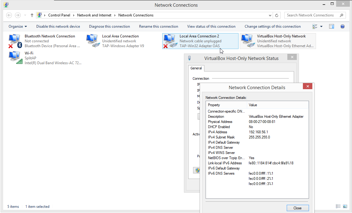
Set the Windows Host Only Network IP Address in the script.
WINDOWS_VM_GRE_WINGATEWAY="192.168.245.1"
Step 3: Upload Tunnel Script
Upload your tunnel script. This can be done via SFTP or by pasting it into a server text editor such as nano.
nano /etc/tunnel.sh
Make the script executable:
chmod +x /etc/tunnel.sh
Step 4: Test
Run the script.
bash /etc/tunnel.sh
Test that the tunnel is online by pinging the gateway IP. If pingable, proceed. Else proceed to troubleshooting.
Step 5: Run on boot
In /etc/rc.local before exit 0 add:
/etc/tunnel.sh
The tunnel will now be created on boot.
Part 3: Windows Setup
- Default Gateway
- Interface Metric (high)
How this works
For an overview of the process, see Figure 1. More in-depth details are available in the later figures.
Figure 1: Network Overview
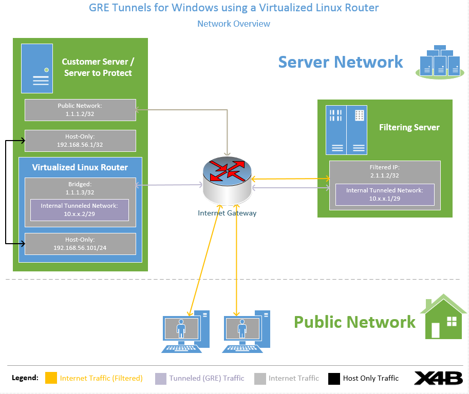
Process:
- Connecting Client sends packet to Filtered IP Address. The filtering server marks this packet as clean and to be passed on to the backend server.
- The filtering server encapsulates the packet in GRE and sends it to the Backend Server's (Customer Server) Linux VM assigned IP. This is the IP assigned to the bridged interface.
- The Linux VM de-encapsulates the payload from the GRE packet.
- The packet is delivered at the Windows Host Machine via the Host-Only Network. The packet is addressed to the Windows Host-Only address (i.e. 192.168.56.1) and any process listening on that port can reply.
Note:
In this diagram the Windows VM has a network address of 1.1.1.1 that is not used for filtering, this is intentional and to allow for continued access to services such as RDP.
Figure 2: Client Packet Rewrite Process (Filter -> Backend)
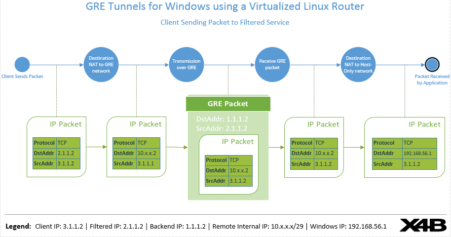
Process:
- The IP packet from the public client is received at the filtering location. It is accepted as clean traffic to be forwarded to the backend.
- The destination address of the packet is re-written so that it will be sent over the GRE tunnel between the Filtered Service and the Backend Linux Virtual Machine.
- The IP packet is encapsulated (in GRE) and sent to the Linux Virtual Machine
- The Linux Virtual Machine receives the GRE packet and de-encapsulates it.
- The Destination Address of the IP packet is re-written to reflect the address of the Windows PC on the Host-Only-Network that this packet will be delivered to. The packet is then hence delivered to the Windows PC, via the Host-Only-Network adapter.
Figure 3: Client Packet Reverse Rewrite Process (Backend -> Filter)
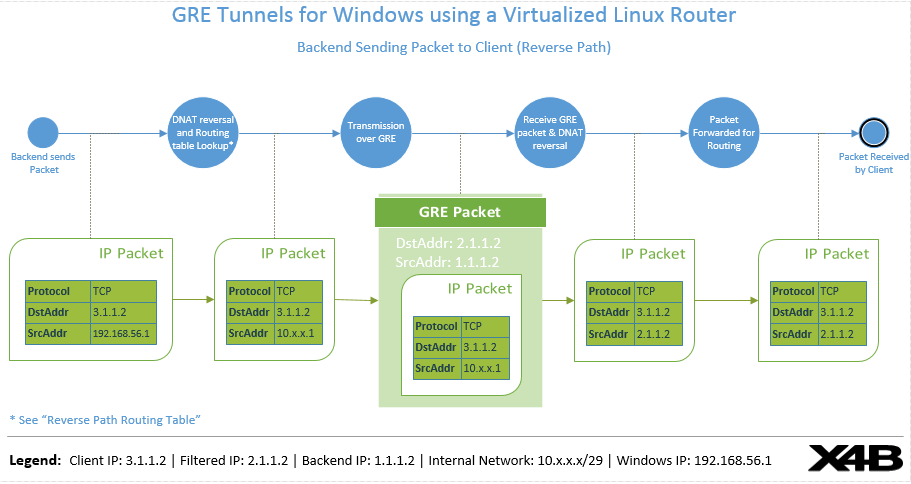
Process:
- A packet is sent from the Windows Virtual Machine addressed to an address on the internet over the Host-Only-Network. This may be a response to an incoming packet from the client or a new connection made via the Tunnel (e.g a game server registering itself with a service like Steam).
- The packet is received by the Linux Virtual Machine. The source address is re-written to match a packet that is being sent on the GRE tunnel, originating from the VM endpoint itself.
- The encapsulated packet is sent to the filtered IP.
- The encapsulated packet is received at the filtering server and de-encapsulated.
- The packet is Source address is re-written to reflect a packet originating from the filter itself.
- The packet is then delivered to the intended destination (such as the connecting client or internet server).
Figure 4: Reverse Path Routing Table
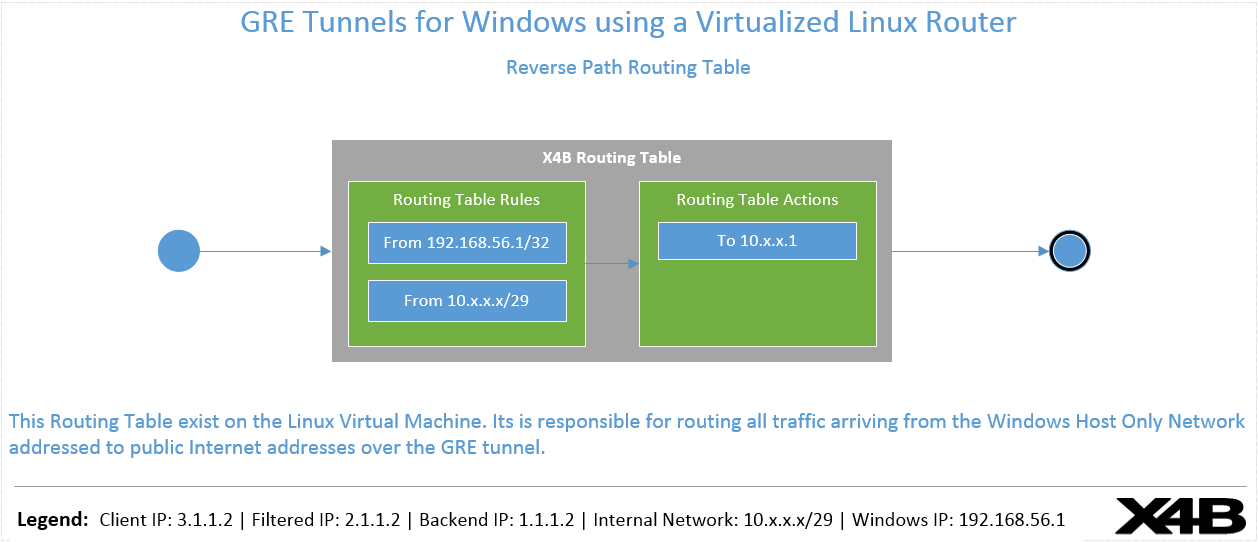
The routing table ensures that all traffic originates from the windows Host-Only-Network adapter is sent over the GRE tunnel. Without this traffic would be sent over the default route and rejected at upstream routers.